
Custom PEEK CNC Machining
CNC-milled and CNC-turned PEEK components built around your drawing, material grade, dimensional requirements and end-use conditions. Review manufacturability before requesting a quote.
Upload Drawing for Quote →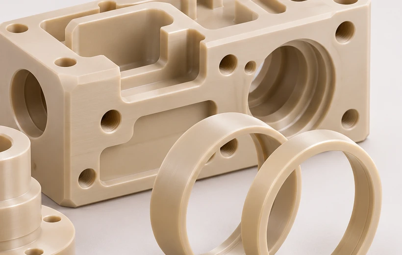 Illustrative product rendering
Machined PEEK parts require polymer-specific process planning.
PEEK is machinable, but clamping force, temperature, cutting heat and residual stress can affect critical dimensions. Different geometries call for different machining routes.
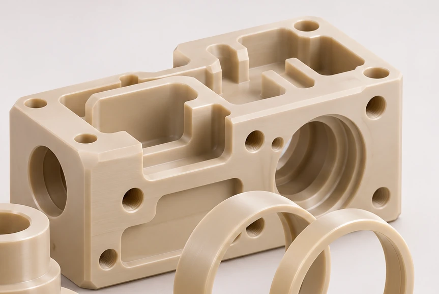
PEEK CNC milling
For pockets, flat interfaces, multi-axis holes, slots and complex housings. The DFM review should flag deep pockets, long-reach cutters, thin walls and uneven stock removal.
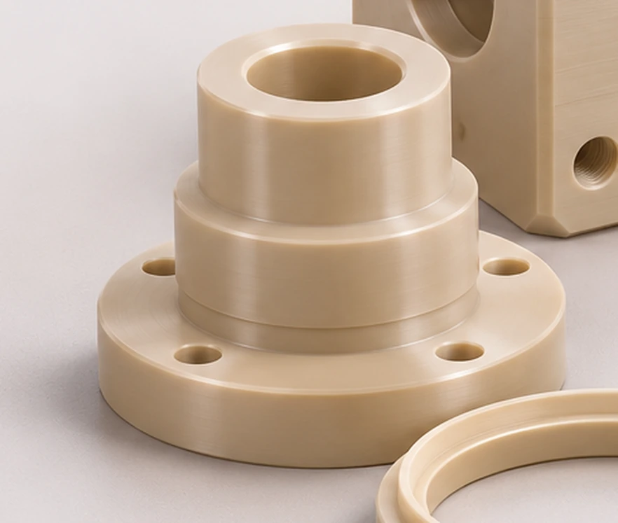
PEEK CNC turning
For concentric parts such as bushings, sleeves, spacers and sealing rings. Bore-to-OD relationships, parting method, deformation under jaw pressure and ring roundness matter.
Unfilled, GF30 and CF30 are not interchangeable.
Confirm the exact manufacturer grade, stock form and documentation requirements before quotation.
| Material family | Machining / procurement implications |
|---|---|
| Virgin / unfilled PEEK | Specify the exact grade, application media and critical dimensional requirements. Check thermal expansion and insulation needs. |
| GF30 (30% glass-filled PEEK) | Higher stiffness is often relevant, but fibre reinforcement affects tool wear, surface appearance and mating-surface considerations. Confirm the actual datasheet. |
| CF30 (30% carbon-filled PEEK) | Consider stiffness, wear pairing and possible change in electrical properties. Review fibre direction, machining finish and traceability. |
| Any supplied stock | Agree rod/plate dimensions, stress-relief condition, stock manufacturer, batch documentation and any required re-anneal sequence. |
“GF30” and “CF30” refer to nominal 30% fibre-filled material families; always quote the exact commercial grade.
DFM risks: assess features before promising a tolerance.
On PEEK, non-uniform material removal and clamping are as important as machine travel or nominal tool accuracy.
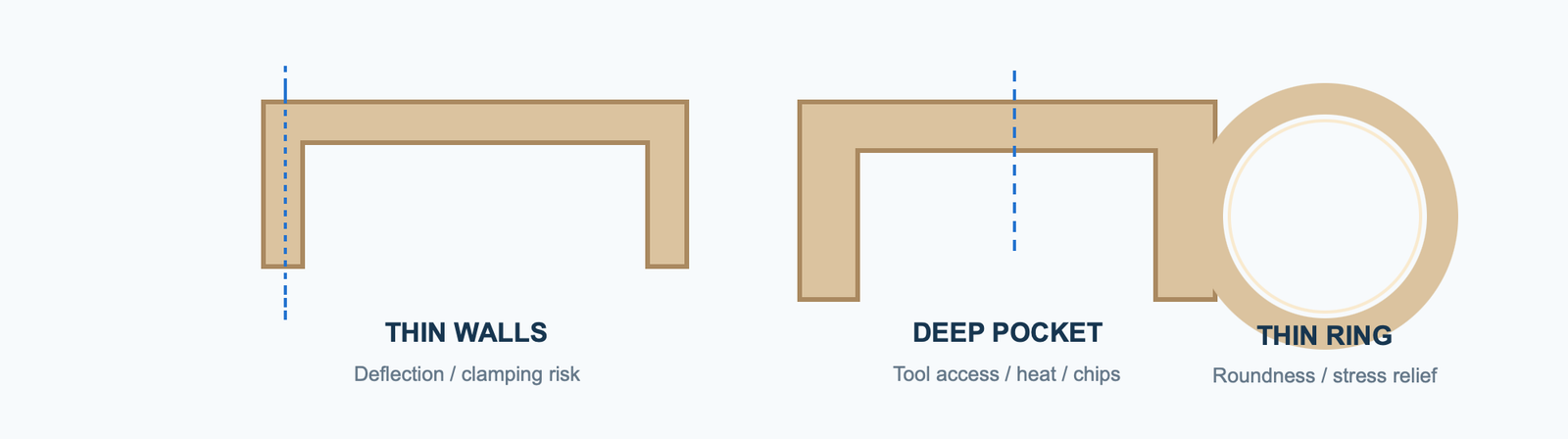
Thin walls & slots
Thin sections can deflect when clamped or cut. Identify minimum walls, unsupported spans, datum faces and acceptable bow / flatness.
Deep pockets & long tools
Check depth-to-width ratio, internal corner radii, tool access, chip evacuation and potential heat buildup.
Stress & stability
Heavy asymmetric removal can release residual stresses. Intermediate stress relief should be evaluated for demanding parts and only specified after grade/stock review.
Threads & edge features
Clarify internal thread class, number of assembly cycles, minimum edge distance, chamfers and deburring.
Mating interfaces
Distinguish functional fits and GD&T requirements from cosmetic dimensions; avoid applying unnecessarily tight tolerances to all features.
Measurement approach
Check inspection temperature, fixturing, gauge contact pressure and suitable measuring equipment for every critical feature.
Inspection requirements belong on the drawing.
Tolerance and inspection requirements depend on the part geometry, material grade and acceptance conditions.
| Critical feature | Quote / acceptance requirements |
|---|---|
| Critical bores, IDs and ODs | Specify nominal size, tolerance, roundness, fit, material grade and stabilized inspection condition. |
| Flatness / parallelism | Reference datums, relaxed vs clamped state, measurement setup and geometry-dependent feasibility. |
| Position / threads / features | Define datum scheme, true-position or thread callout, machining direction and deburring requirements. |
| Surface & appearance | Specify functional surface finish, edge break, scratches and acceptable fibre exposure where relevant. |
| Inspection documents | Identify drawing revision and which items require a report, certificate, traceability or separate functional test. |
Illustrative DFM review: a pocketed PEEK fixture
This example shows how a pocketed PEEK fixture can be reviewed for geometry, machining risks and inspection requirements.
Initial geometry
A thick rectangular blank contains a broad off-centre pocket, a thin remaining floor and precision mounting bores.
What could go wrong
One-sided material removal may release stock stress; deep machining and concentrated clamping can distort the floor or shift bore inspection results.
What to discuss
Evaluate balanced removal, fixture support, rough/finish sequence and whether intermediate stress relief is appropriate for the specified grade and stock.
How to verify
Agree drawing datums, critical bore/flatness checks and inspection condition before committing to tolerance or documentation.
Material × geometry × process × inspection decision matrix
Use the matrix to determine the questions to ask, not to infer a universal tolerance or automatic material recommendation.
| Decision axis | Buyer input | Review focus / trade-off | Verification before order |
|---|---|---|---|
| Material | Exact grade, reinforcement and stock origin | Unfilled vs glass-/carbon-filled PEEK differ by supplier data, material orientation and cutting behaviour. | Grade-specific TDS, stock form and required material records |
| Geometry | Thin walls, deep pockets, long bores, asymmetric removal | Fixturing loads, access, heat and stress redistribution affect process planning. | Critical dimensions, datums, feature accessibility and orientation |
| Process | Milled vs turned features; blank allowances | Sequence, tool access and whether relief between stages is justified. | Proposed process review; no published blanket lead time |
| Inspection | Bore/OD fit, flatness, feature position and surface requirements | Measurement support and temperature can alter observed results. | Drawing-based acceptance method and report scope |
Grade family descriptions are comparisons only; 450G, 450GL30 and 450CA30 are specific Victrex resin grades, not interchangeable guarantees for machined stock.
What can be discussed from a drawing.
Illustrative examples of PEEK component geometries.
Housings & fixtures
Multiface pockets, mounting holes and functional datums.
Bushings & sleeves
Turned OD, bores, fit and concentricity considerations.
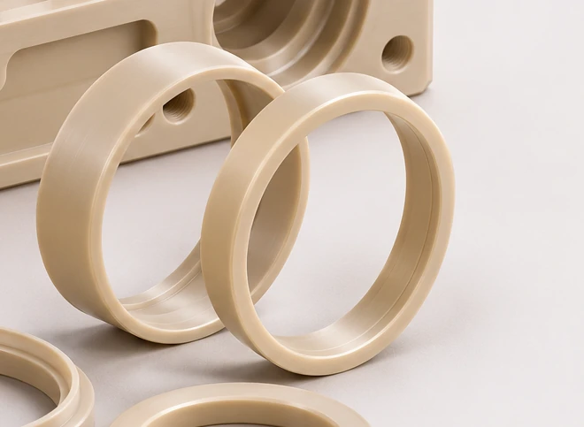
Spacers & rings
Profile, flatness and wall-section requirements.
CNC drawing review checklist.
Use this as a printable checklist before sharing a machining RFQ.
Include these six items
Frequently asked machining questions.
Why can a tight bore tolerance be harder on PEEK than on metal?
Polymer thermal expansion, compliance during clamping, and material stress can affect the measured diameter. Agree the grade, geometry, datum and inspection conditions before promising a tolerance.
Should every machined PEEK part be annealed?
Not necessarily. Starting stock condition, the amount and asymmetry of material removal, section thickness and final dimensional requirements determine whether intermediate stress relief should be evaluated.
Which drawings are most helpful for a CNC quotation?
A dimensioned PDF with the current revision, optional STEP geometry, material grade, quantity, functional tolerances, surface finish and inspection requirements.
What is the difference between virgin PEEK, GF30 and CF30?
Unfilled PEEK and 30% glass- or carbon-filled grades vary in stiffness, wear interactions, electrical behavior and machinability. Compare actual supplier data sheets, not the polymer family name alone.
Source scope: The links below provide general third-party engineering guidance. Confirm material selection, drawings and application requirements for your project.
Independent technical guidance for preliminary engineering discussion; material and assembly specifications govern the final component.