
Custom PEEK Back-up Rings
Solid, split and scarf-cut PEEK anti-extrusion support rings manufactured to the specified gland and seal assembly geometry. The ring supports a primary sealing element; it is not itself the primary seal.
Upload Drawing for Quote →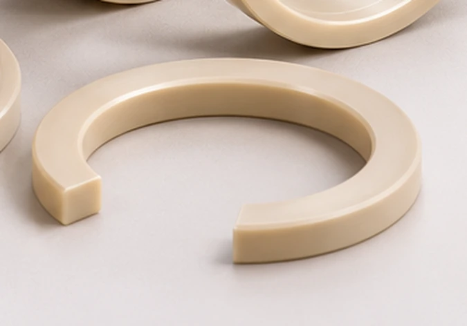 Illustrative product rendering
Solid, split and scarf-cut rings serve different installation needs.
The selected cut influences installation clearance and fit. The final configuration and tolerances must match the approved gland drawing.
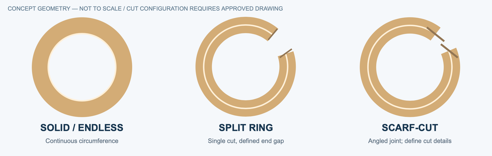
Solid / endless
No cut across the circumference; installation feasibility depends on assembly access and the specified geometry.
Single split
A discrete joint to facilitate installation; define split position, gap at inspection and acceptable end geometry.
Scarf-cut
Angled joint geometry; cut angle and overlap profile must be specified, not inferred from a generic product photo.
Annotate ID, OD, section and axial width separately.
Reference sketches are illustrative. Submit the approved 2D/3D drawing for manufacture; values and tolerance zones cannot be inferred from this diagram.
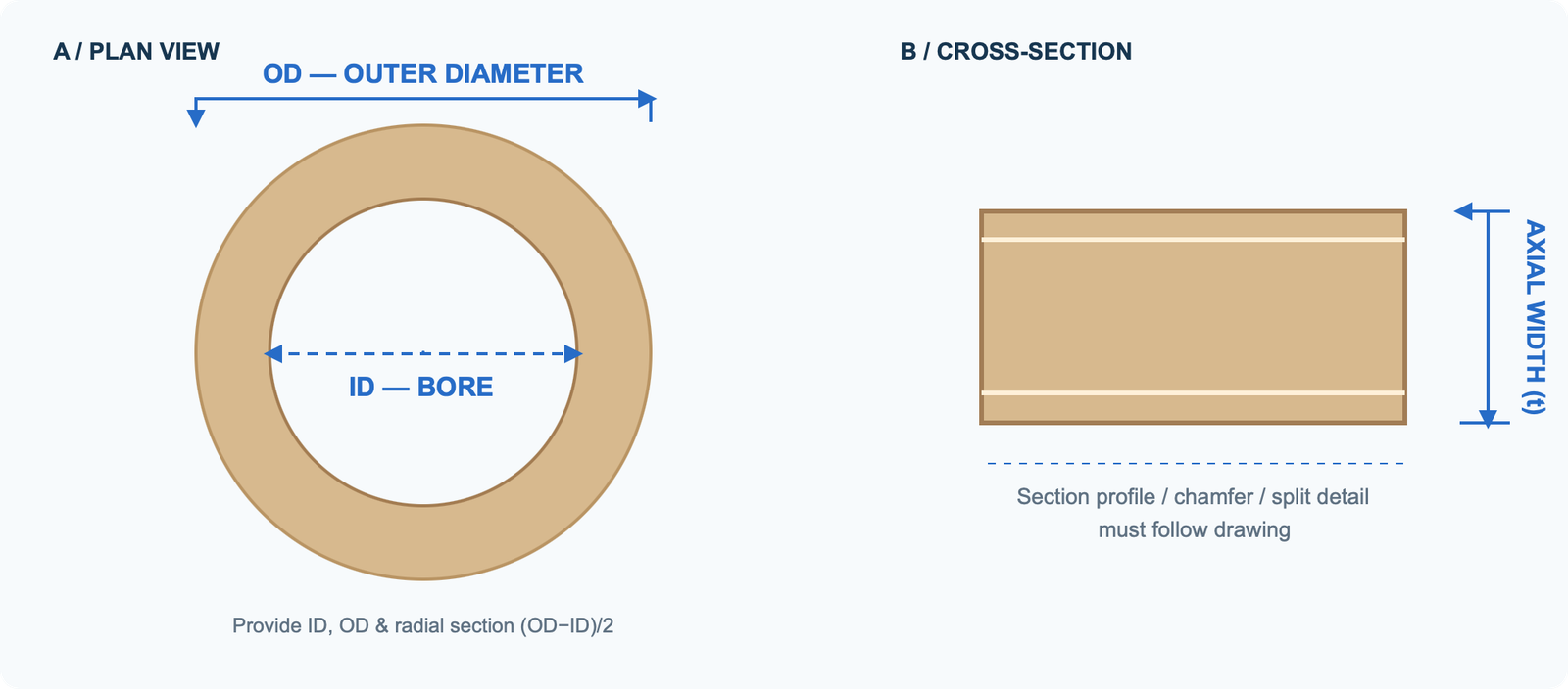
| Drawing callout | Definition / purchasing note |
|---|---|
| ID — inner diameter | Nominal bore size; assembled fit, thermal state and tolerance |
| OD — outer diameter | Outer mating diameter; dimensional tolerance and free-state / installed-state requirement |
| Radial cross-section | (OD − ID) / 2 for a concentric simple rectangular annulus; custom profiles require a defined section drawing |
| Axial thickness / width | Specify nominal thickness, tolerance, side-face finish and edge treatment |
| Split or scarf details | Specify cut type, end gap, angular details and inspection condition |
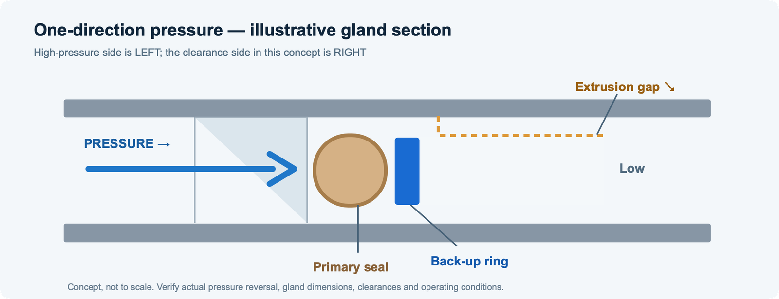
A back-up ring protects the seal from extrusion into a clearance gap.
For unidirectional pressure, the back-up ring is generally placed downstream of the primary seal, where extrusion is a concern. Reversing pressure can change the required ring arrangement.
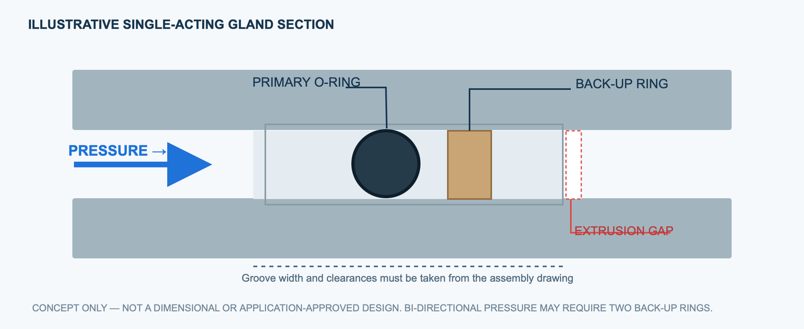
Groove width
Include total space for the primary seal and any back-up rings in the actual assembly arrangement.
Extrusion gap
Specify maximum clearance under pressure, thermal change and tolerance accumulation.
Pressure direction
State whether pressure is one-way, reversing or bi-directional. Two back-up rings may be needed in some arrangements.
Counterpart geometry
Specify piston/rod orientation, gland surfaces and assembly constraints.
Solid vs split vs scarf-cut: installation trade-offs
The cut style changes the installation sequence and end-gap behaviour. A drawing of the assembly and groove is still necessary.
| Construction | Typical design consideration | Buyer must specify | Selection boundary |
|---|---|---|---|
| Solid / uncut | Continuous ring; assembly access must permit installation. | ID/OD, axial width, section and how the ring reaches the gland. | Do not assume it can be stretched over a shoulder. |
| Single split | One joint can ease assembly where continuous installation is difficult. | Split orientation, end gap at installed condition and permitted joint geometry. | A split is not automatically suitable for every extrusion-gap configuration. |
| Scarf-cut | Angled joint may change the gap path at the interface. | Cut angle, overlap concept, assembled gap and inspection criteria. | Not a guaranteed leakage or pressure improvement without system validation. |
Direction and reversals
Mark upstream and downstream sides. In a single-direction system, the anti-extrusion support is typically considered at the lower-pressure clearance side of the primary seal.
Width and section
Provide groove depth/width, clearances and actual tolerance stack with the installed seal, not only the loose-ring nominal dimensions.
Stress and function
Evaluate deformation, mating hardware and service conditions as an assembly; approval requires application engineering and testing where necessary.
Pressure direction, primary seal and extrusion gap
The concept diagram illustrates the location relationship under one-way pressure. Reverse or alternating pressure can change where supports are required.
| RFQ dimension | Description | Required from buyer |
|---|---|---|
| Groove width and depth | Space available for the complete sealing stack. | Tolerance and datum for assembled hardware |
| Extrusion gap | Maximum opening where the primary seal could enter clearance. | Worst-case hardware clearance including load/thermal effects |
| Pressure direction | Which side is pressurised; whether direction reverses. | Single-/double-acting cycle and pressure peaks (buyer data only) |
| Ring geometry | ID, OD, axial width, section and split profile. | Installed dimensions, material grade and related seal geometry |
The dimensions required to quote a custom ring.
This is a practical procurement sheet, not a pre-approved sealing design.
Include these seven details
Common back-up ring design questions.
Are PEEK back-up rings the same as PEEK sealing rings?
No. A back-up ring primarily provides anti-extrusion support to a primary seal. It is specified as a component of the complete gland and sealing assembly.
Where is a back-up ring installed relative to an O-ring?
Placement depends on pressure direction and gland design. In a single-acting configuration, it is generally installed on the low-pressure / downstream side; reversing duty may need rings on both sides.
What determines whether a split ring can be used?
Installation access, joint geometry, groove dimensions, sealing-element design and pressure/clearance limits all affect the cut selection.
Can OD, ID and thickness alone determine a safe design?
No. The maximum extrusion gap, pressure direction, seal hardness/profile, temperature and assembly tolerances are also required.
Source scope: The links below provide general third-party engineering guidance. Confirm material selection, drawings and application requirements for your project.
Independent technical guidance for preliminary engineering discussion; material and assembly specifications govern the final component.